Yagi antenna calculator (DL6WU)
About
This calculator works out the dimensions of a Yagi antenna using the DL6WU method. The Yagi-Uda is the most popular type of directional antenna for the VHF and UHF bands. The calculator takes the correction for the influence of the boom into account, along with different types of element mounting.
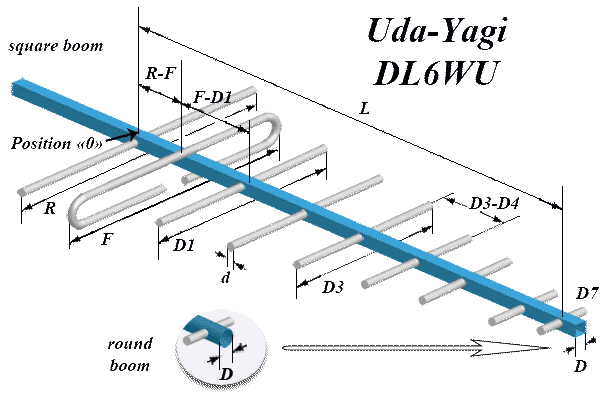
Схема Yagi антени: петльовий диполь, круглі елементи
| ||||||||||||||||||||||||||||||
Notes
- Standard frequencies: pick one from the list of common frequencies or enter your own by hand.
- Driven element shape: a folded dipole gives a better match (75 Ω), a split dipole has an impedance of about 50 Ω.
- Element type: round elements are simpler to make, flat ones have slightly better characteristics.
- Boom shape: a round or square boom cross-section affects the correction calculation.
- Element mounting:
- Option 1: elements bonded to a metal boom (the simplest construction)
- Option 2: elements insulated from the boom (better characteristics)
- Option 3: a dielectric boom or elements spaced away from it (the best characteristics)
- Units: results can be shown in millimetres, centimetres or metres.
- The minimum number of elements is 3 (reflector + dipole + 1 director).
- The maximum number of elements is capped at 20 for practical reasons.
- The boom diameter should not exceed 9% of the wavelength.
- The calculation includes boom correction according to the DL6WU algorithm.
- Gain is calculated from empirical formulas and is approximate.
- For fine tuning, an SWR meter and an antenna analyser are recommended.
Calculator by UR3PKI
The most recent versions are available on the author's site: CYBERDEV.SPACE - Yagi antenna (DL6WU)